Aluminum Busbar Ampacity
When designing electrical distribution systems, selecting the correct aluminum busbar ampacity is critical for safety, efficiency, and long-term reliability. Whether you're an electrical engineer, contractor, or facility manager, understanding busbar current ratings can prevent costly failures and ensure optimal system performance.
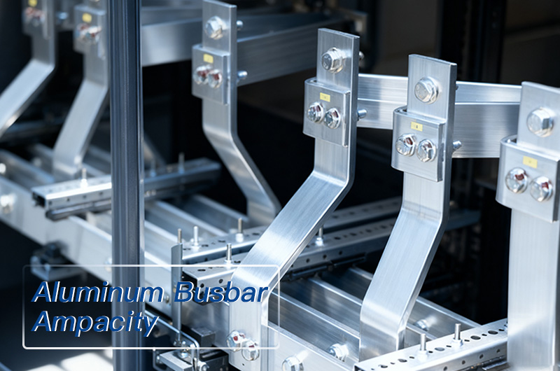
This comprehensive guide provides detailed aluminum busbar ampacity charts, technical specifications, and practical selection criteria to help you make informed decisions for your electrical projects.
What is Aluminum Busbar Ampacity?
Busbar ampacity refers to the maximum continuous current-carrying capacity of a busbar conductor under specific operating conditions without exceeding temperature limits. For aluminum busbars, this rating depends on several critical factors:
- Cross-sectional area (thickness × width)
- Material conductivity (typically Aluminum 6101-T61)
- Ambient temperature and temperature rise
- Installation orientation (vertical vs. horizontal)
- Current type (AC vs. DC)
- Number of parallel bars
- Ventilation and heat dissipation conditions
Why Aluminum Busbars?
Aluminum busbars offer significant advantages in modern electrical installations:
Cost-Effective: 60-70% less expensive than copper alternatives
Lightweight: Approximately 70% lighter than copper busbars
Corrosion Resistant: Excellent performance in harsh environments
Adequate Conductivity: 61% IACS conductivity meets most applications
Easy Installation: Reduced weight simplifies handling and mounting
Aluminum 6101-T61: The Industry Standard Alloy
Aluminum 6101-T61 is the preferred alloy for electrical busbar applications due to its optimized balance of:
- High electrical conductivity(minimum 61% IACS)
- Excellent mechanical strength(T61 temper)
- Superior corrosion resistance
- Good formability and machinability
- Thermal stabilityfor continuous operation
Key Specifications
| Property | Value |
| Electrical Conductivity | ≥61% IACS |
| Temperature Coefficient | 0.00403/°C at 20°C |
| Density | 2.70 g/cm³ (0.0975 lb/in³) |
| Melting Point | 582-652°C (1080-1206°F) |
| Thermal Expansion | 23.6 × 10⁻⁶/°C |
Aluminum Busbar Ampacity Chart: Standard Sizes
Single Bar Ampacity Ratings (60Hz AC)
Understanding the aluminum busbar current ratingfor various sizes is essential for proper system design. Below are the most common configurations:
Popular Busbar Sizes and Their Ampacity
Small to Medium Applications (100-500A)
| Size | 30°C Rise | 50°C Rise | 65°C Rise | Typical Applications |
| 1/8" × 2" | 277A | 370A | 426A | Panel feeders, sub-panels |
| 1/4" × 2" | 398A | 526A | 616A | Switchgear, distribution boards |
| 3/8" × 2" | 493A | 644A | 756A | Industrial machinery, motor control centers |
Medium to Large Applications (500-1500A)
| Size | 30°C Rise | 50°C Rise | 65°C Rise | Typical Applications |
| 1/4" × 4" | 700A | 952A | 1092A | Main distribution, transformer secondaries |
| 3/8" × 4" | 840A | 1120A | 1316A | Substations, power distribution units |
| 1/2" × 4" | 952A | 1288A | 1484A | Heavy industrial, data centers |
High Current Applications (1500A+)
| Size | 30°C Rise | 50°C Rise | 65°C Rise | Typical Applications |
| 1/2" × 6" | 1344A | 1764A | 2044A | Electroplating, welding equipment |
| 1/2" × 8" | 1680A | 2240A | 2576A | Smelters, large industrial processes |
Temperature Rise Explained
The temperature rise indicates how much hotter the busbar operates above ambient temperature:
- 30°C Rise: Conservative rating for enclosed spaces, poor ventilation, or safety-critical applications
- 50°C Rise: Standard industrial rating for typical installations with normal ventilation
- 65°C Rise: Maximum rating for well-ventilated, open-air installations
Important: Always verify that insulation materials, mounting hardware, and adjacent components can withstand the selected temperature rise.
Factors Affecting Aluminum Busbar Ampacity
Cross-Sectional Area
The most significant factor in determining ampacity is thecross-sectional areaof the busbar. Doubling the cross-section doesn't double the ampacity due to thermal considerations—typically increases range from 70-85%.
Installation Orientation
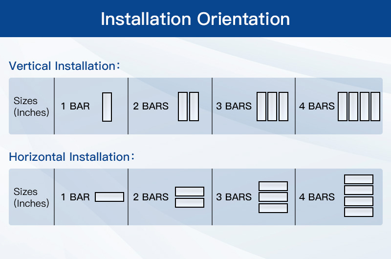
Vertical Installation (Edge-Mounted)
- Superior heat dissipation through natural convection
- Hot air rises away from conductor
- 10-15% higher ampacity compared to horizontal mounting
- Recommended for high-current applications
Horizontal Installation (Flat-Mounted)
- Reduced natural convection
- Heat trapped beneath conductor
- Lower ampacity ratings
- May require forced air cooling for high loads
Ampacity Comparison Example(1/2" × 6" busbar):
| Orientation | 1 Bar AC | 2 Bars AC | 3 Bars AC | 4 Bars AC |
| Vertical | 1892A | 3230A | 4278A | 5210A |
| Horizontal | 1710A | 2800A | 3080A | 3930A |
| Difference | +10.6% | +15.4% | +38.9% | +32.6% |
AC vs DC Current
DC Ampacity is generally higher because:
- Uniform current distribution across entire cross-section
- No skin effect or proximity effect
- Simpler thermal calculations
AC Ampacity is reduced due to:
- Skin Effect: Current concentrates near surface at 60Hz
- Proximity Effect: Adjacent conductors influence current distribution
- Harmonic Losses: Non-linear loads increase effective resistance
Typical Derating: AC ampacity is 5-25% lower than DC, increasing with busbar size and frequency.
Multiple Parallel Bars
Using multiple parallel busbars increases total ampacity but not proportionally:
Derating Factors:
- 2 bars: ~90-95% of double single-bar rating
- 3 bars: ~80-90% of triple single-bar rating
- 4 bars: ~70-85% of quadruple single-bar rating
Example Calculation(1/4" × 4" vertical AC):
| Configuration | Theoretical | Actual | Efficiency |
| 1 bar | 1184A | 1184A | 100% |
| 2 bars | 2368A | 2092A | 88.3% |
| 3 bars | 3552A | 2905A | 81.8% |
| 4 bars | 4736A | 3625A | 76.5% |
How to Calculate and Select Aluminum Busbar Ampacity
Step-by-Step Selection Process
Step 1: Determine Required Current
- Calculate maximum continuous load current
- Add 25% safety margin for future expansion
- Consider starting currents for motors and transformers
Step 2: Identify Operating Conditions
- Ambient temperature (typically 40°C for enclosed spaces)
- Available ventilation (natural or forced)
- Acceptable temperature rise
- Installation space constraints
Step 3: Choose Temperature Rise Rating
- Safety-critical systems: 30°C rise
- Standard installations: 50°C rise
- Well-ventilated areas: 65°C rise
Step 4: Select Busbar Size
- Refer to aluminum busbar ampacity charts
- Choose next larger size if between ratings
- Verify physical dimensions fit available space
Step 5: Apply Derating Factors
- High ambient temperature: Reduce by 1-2% per °C above 40°C
- Poor ventilation: Use 30°C rise rating or increase size
- Harmonic loading: Reduce by 10-20% for non-linear loads
- Multiple bars: Apply proximity derating factors
Selection: 3/8" × 4" aluminum busbar at 50°C rise provides 1120A capacity with 12% margin.
Aluminum Busbar Sizing Chart by Application
Commercial Buildings
| Application | Typical Current | Recommended Size | Temperature Rise |
| Lighting Panels | 100-200A | 1/8" × 2" | 50°C |
| Sub-distribution | 200-400A | 1/4" × 2" | 50°C |
| Main Distribution | 400-800A | 1/4" × 4" or 3/8" × 3" | 50°C |
| Service Entrance | 800-1600A | 1/2" × 4" to 1/2" × 6" | 50°C |
Industrial Facilities
| Application | Typical Current | Recommended Size | Temperature Rise |
| Motor Control Centers | 400-600A | 1/4" × 3" to 3/8" × 2" | 50°C |
| Process Equipment | 600-1200A | 3/8" × 4" to 1/2" × 4" | 50°C |
| Main Bus | 1200-2000A | 1/2" × 6" to 1/2" × 8" | 50-65°C |
| Transformer Secondary | 1500-3000A | Multiple 1/2" × 6" bars | 50°C |
Data Centers
| Application | Typical Current | Recommended Size | Temperature Rise |
| PDU Feeders | 400-800A | 1/4" × 4" to 3/8" × 3" | 30-50°C |
| UPS Output | 800-1600A | 3/8" × 5" to 1/2" × 5" | 30°C |
| Main Distribution | 1600-3200A | Multiple 1/2" × 6" bars | 30-50°C |
Installation Best Practices for Optimal Ampacity
Mounting Guidelines
1. Orientation Selection
- Vertical mountingpreferred for currents >400A
- Orient wide dimension vertically for best cooling
- Maintain minimum 2" clearance to walls/enclosures
2. Spacing Between Bars
- Single bars: Minimum 1× width spacing
- Multiple parallel bars: 0.5-1× thickness spacing
- Stagger joints to prevent hot spots
3. Support and Hardware
- Use aluminum or tin-plated copper hardware
- Support every 24-36 inches vertically
- Support every 18-24 inches horizontally
- Avoid direct contact with ferrous materials
Connection Techniques
Joint Resistance: Connection resistance must be minimized:
- Clean surfaces thoroughly before assembly
- Use anti-oxidant compound on all mating surfaces
- Apply proper torque per manufacturer specifications
- Use belleville washers to maintain pressure
Bolted Connections:
Recommended Torque Values:
- 1/4" bolts: 75-100 in-lbs
- 5/16" bolts: 132-180 in-lbs
- 3/8" bolts: 240-300 in-lbs
- 1/2" bolts: 450-600 in-lbs
Thermal Management
Ventilation Requirements:
- Natural convection: Minimum 4" clearance top/bottom
- Forced air cooling: 200-400 CFM per kW heat dissipation
- Enclosed spaces: Temperature monitoring recommended
Comparing Aluminum vs Copper Busbar Ampacity
Size Equivalency
To achieve similar ampacity, aluminum busbars must be larger than copper:
| Copper Size | Copper Ampacity | Equivalent Aluminum | Aluminum Ampacity |
| 1/4" × 2" | 575A | 1/4" × 3" | 554A |
| 1/4" × 3" | 785A | 3/8" × 3" | 672A |
| 1/4" × 4" | 1000A | 3/8" × 4" | 840A |
| 3/8" × 4" | 1200A | 1/2" × 4" | 952A |
Cost-Benefit Analysis
Aluminum Advantages:
- 60-70% lower material cost
- 70% lighter weight (reduced structural requirements)
- Lower installation labor costs
- Easier to work with and modify
Copper Advantages:
- Smaller physical size for same ampacity
- Lower resistance = less voltage drop
- Better for space-constrained applications
- Longer service life in harsh environments
Break-Even Analysis:
For most applications >200A, aluminum provides 30-50% total cost savings
despite larger size requirements.
Common Mistakes to Avoid
Undersizing Busbar
Problem: Using ampacity at maximum temperature rise without safety margin
Solution: Add 20-25% capacity for future loads and transients
Ignoring Ambient Temperature
Problem: Using 40°C ambient ratings in 50°C+ environments
Solution: Derate 1-2% per °C above rated ambient temperature
Poor Joint Quality
Problem: High resistance connections cause localized overheating
Solution: Follow proper surface preparation and torque specifications
Mixing Metals
Problem: Aluminum-to-copper connections cause galvanic corrosion
Solution: Use tin-plated copper hardware and anti-oxidant compound
Inadequate Support
Problem: Mechanical stress causes joint failure and hot spots
Solution: Support per specifications and allow for thermal expansion
Frequently Asked Questions (FAQ)
Q: Can I use aluminum busbar outdoors?
A: Yes, aluminum 6101 has excellent corrosion resistance. However:
- Use appropriate IP-rated enclosures
- Protect connections from moisture
- Consider additional corrosion protection in coastal areas
- Regular inspection and maintenance required
Q: What's the maximum length for a busbar run?
A: Length is limited by:
- Voltage drop: Typically <3% for feeders, <5% total
- Mechanical support: Expansion joints needed >30 feet
- Thermal expansion: 0.0014 inches per foot per 10°C rise
Calculate voltage drop:VD = 2 × I × R × L
Q: How does high-frequency current affect ampacity?
A: Skin effect increases with frequency:
- 60Hz: Standard ratings apply
- 400Hz: Reduce ampacity by 10-15%
- 1kHz: Reduce ampacity by 20-40%
- Use specialized calculations for frequencies >1kHz
Q: Can I increase ampacity with forced cooling?
A: Yes, forced air cooling can increase ampacity by:
- 15-25% with moderate airflow (100-200 CFM)
- 30-50% with high-velocity forced cooling
- Requires engineering analysis and permanent cooling system
- Not recommended as primary design strategy
Q: What standards govern busbar ampacity ratings?
A: Key standards include:
- IEEE 605: Guide for Bus Design in Air-Insulated Substations
- IEC 61439: Low-voltage switchgear and controlgear assemblies
- UL 857: Busways and associated fittings
- NEMA BU 1: Busway standards
Q: How often should busbars be inspected?
A: Recommended inspection intervals:
- Initial: 6 months after installation
- Normal service: Annually
- Critical applications: Quarterly
- After fault events: Immediately
Use thermal imaging to detect hot spots indicating degraded connections.
Aluminum Busbar Ampacity: Quick Reference Guide
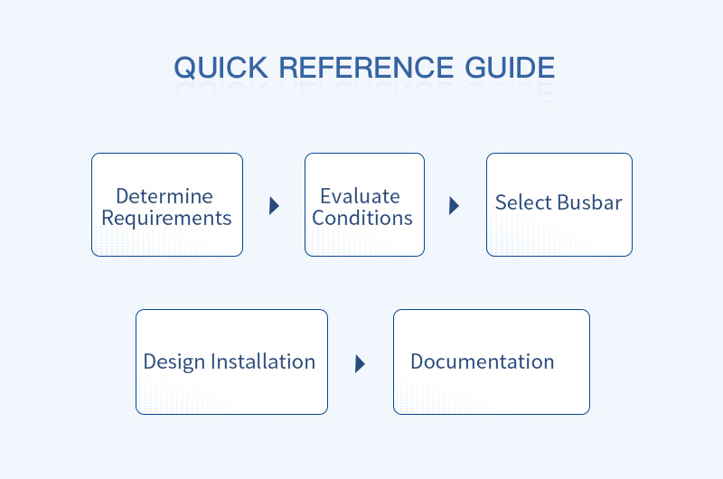
Determine Requirements
- Calculate maximum continuous current
- Identify peak/inrush currents
- Establish ambient temperature
- Define temperature rise limit
Evaluate Conditions
- Assess available ventilation
- Determine mounting orientation
- Check space constraints
- Identify AC or DC application
Select Busbar
- Choose appropriate size from ampacity table
- Apply derating factors
- Verify physical fit
- Confirm connection compatibility
Design Installation
- Plan support locations
- Calculate thermal expansion
- Design joint connections
- Specify hardware and materials
Documentation
- Create as-built drawings
- Document torque values
- Establish inspection schedule
- Record thermal baseline
Conclusion: Maximizing Performance with Proper Aluminum Busbar Selection
Selecting the correct aluminum busbar ampacity is fundamental to electrical system safety, reliability, and cost-effectiveness. By understanding the factors that influence current-carrying capacity—including temperature rise, installation orientation, AC vs. DC operation, and multiple bar configurations—you can design optimized power distribution systems.
Key Takeaways:
- Use Accurate Data: Always reference verified ampacity tables for Aluminum 6101-T61
- Apply Safety Margins: Design for 25% above maximum continuous load
- Consider All Factors: Temperature rise, orientation, and ventilation significantly impact performance
- Quality Installation: Proper connections and support are critical for achieving rated ampacity
- Regular Maintenance: Thermal imaging and joint inspections prevent failures
Ready to Specify Aluminum Busbars for Your Project?
Whether you're designing a new electrical distribution system or upgrading existing infrastructure, proper busbar selection ensures:
- Safe, reliable operation within thermal limits
- Optimized material costs and installation efficiency
- Long-term performance and minimal maintenance
- Compliance with electrical codes and standards
Need Expert Assistance?
Our technical team can help you:
- Verify busbar sizing calculations
- Recommend optimal configurations
- Provide custom ampacity analysis
- Source high-quality aluminum 6101 busbars
Contact us today for a free consultation and quote on your aluminum busbar requirements.
